Interface your Mote to a Thermocouple
We use the DC9005 Eterna QuikEval Adapter to connect the mote to an LTC2984 Multi-Sensor High Accuracy Digital Temperature Measurement System Demo Board to read a K-type thermocouple.
Introduction
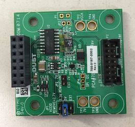
This recipe covers the upcoming DC9005 Eterna QuikEval Adapter - it allows your OCDK application to talk to any of the Linear demo boards that support the DC590B interface. It does not currently support using the QuikEval GUI tools for driving the demo, but it allows for OCSDK firmware development for a wide variety of linear ICs without having to spin a board.
Figure 1 - The DC9005
Hardware Connection
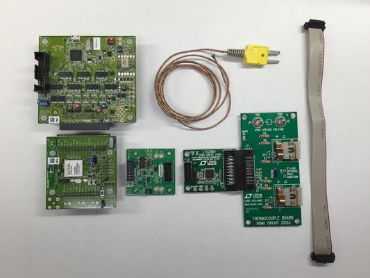
In our sample, we use the DC9003 Evaluation Kit mote, connected to a DC9006 Interface board. The DC9006 provides power for the mote and the target demoboard through the DC9005 adapter, as well as giving us access to JTAG programming, SPI programming (via ESP), and the mote CLI.
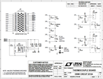
In this demo, the DC9005 plugs into a DC2399A demo circuit which features the LTC2984 24-Bit Precision Digital Temperature Measurement System with EEPROM. In our example, we use the DC2212A dual thermocouple board - it provides two standard thermocouple connectors with onboard diode cold-junction compensation.
Figure 2 - Setup
Software
Portions of this code was adapted from the Linduino C code included in the LTC2984 Demo Software.
The application consists of a single task appTask, that initializes SPI and configures the LTC2984 to read a K-type thermocouple on connector J2, then polls the temperature every 10s. The temperature data is printed on the mote's CLI, and sent to the manager in the same OAP format (see the SmartMesh IP Tools Guide for details) as is used in the TempMonitor SmartMesh SDK Python application. The sample application also has a CLI command to read the "postage stamp" personality I2C EEPROM found on DC590B-compatible demo circuits.
Open the SPI Device
The datasheet states that the LTC2984 expects CPHA = 1, and CPOL = 1. However, the part also accepts CPHA=0 and CPOL=0, which is the default
// open the SPI device
dnErr = dn_open(
                  DN_SPI_DEV_ID,
                  &app_v.spiOpenArgs,
                  sizeof(app_v.spiOpenArgs)
);
ASSERT(dnErr == DN_ERR_NONE);
Open the I2C Device
The DC9005 has a pin that is used to select which bus, I2C or SPI, that will be used to communicate with the target IC. Since all DC590B cards come with an I2C EEPROM that contains device information that is used by QuikEval, we open the I2C. We can simultaneously read the personality EEPROM and the sensor regardless of which bus is selected.
//===== open the I2C device for reading the personality EEPROM
if(app_v.fI2cOpen == CLOSED){
    dnErr = i2cOpen();
    app_v.fI2cOpen = OPEN;
}

// ===== open the BUS_SELECT pin
dnErr = gpioSetMode(BUS_SELECT, DN_IOCTL_GPIO_CFG_OUTPUT, NULL, PIN_LOW);
if (dnErr != DN_ERR_NONE){
      dnm_ucli_printf("bus pin open err=%d\r\n", dnErr);
}

dnErr = gpioWrite(BUS_SELECT, BUS_SPI);
if (dnErr != DN_ERR_NONE){
      dnm_ucli_printf("bus pin write err=%d\r\n", dnErr);
}
OAP Temperature Data
We define a number of structs to carry OAP data - these are packed in order to avoid unexpected padding.
PACKED_START

typedef struct{
   INT8U      control;
   INT8U      id;
}oap_header_t;

typedef struct{
   INT8U      tag;
   INT8U      length;
   INT8U      value;
}oap_channel_t;

typedef struct{
   INT64S     sec;
   INT32S     usec;
}packet_utc_t;      // IAR doesn't pack dn_utc_time_t into the oap_temp_notification_t properly

typedef struct{
   oap_header_t    header;
   INT8U           command;
   INT8U           type;
   oap_channel_t   channel;
   packet_utc_t    timestamp;
   INT32U          rate; //ms
   INT8U           num_samples;
   INT8U           sample_size; //bits
   INT16S          temperature;
}oap_temp_notification_t;
Taking a Temperature Measurement
Each measurement consists of the following steps:
- Set the global config register - the code uses default values for global config and conversion delay, but they are set explicitly for illustration
// -- Set global config register
rwByte(CONFIG_REG, MEM_WRITE, TEMP_UNIT__C | REJECTION__50_60_HZ);
- Set the delay between conversions
// -- Set delay between conversions
rwByte(MUX_REG, MEM_WRITE, 0);
- Channel assignment for sensor - here we select the sensor type (K-type thermocouple, the cold junction reference, and other parameters
//----- Channel 1: Assign Type K Thermocouple -----
channel_assignment_data = SENSOR_TYPE__TYPE_K_THERMOCOUPLE | TC_COLD_JUNCTION_CH__2 | TC_SINGLE_ENDED |
                             TC_OPEN_CKT_DETECT__YES | TC_OPEN_CKT_DETECT_CURRENT__10UA;

assignChannel(CH_1, channel_assignment_data);
- Channel assignment for cold-junction reference
//----- Channel 2: Diode reference -----
channel_assignment_data = SENSOR_TYPE__OFF_CHIP_DIODE | DIODE_SINGLE_ENDED | DIODE_NUM_READINGS__2 |
                             DIODE_AVERAGING_OFF | DIODE_CURRENT__20UA_80UA_160UA | (0x100C49 << DIODE_IDEALITY_FACTOR_LSB);

assignChannel(CH_2, channel_assignment_data);
- Measure the sensor. Wait 500 ms and verify a conversion occurred - this example uses a fixed delay since we aren't in a hurry to take measurements. We could either poll the status register, or wait for the conversion-done interrupt from the LTC2984.
convertChannel(CH_1);
OSTimeDly(500);  // wait 500 ms for conversion to complete instead of polling
rwByte(STATUS_REG, MEM_READ, 0);
- Print the temperature on the CLI and send it in an OAP packet. Temperature is reported by the chip as a signed 24-bit fixed-point (14-bits of integer, 10 bits of fraction) number which must be converted to degrees. OAP normally expects the value to be in 100ths of a °C, but here we return integer °C in order to be able to report a full scale value, which for a K-type thermocouple could be 1250 °C.
rawTemperature = getRawResults(READ_CH_BASE, CH_1);
if(rawTemperature & 0x800000){  // mask off sign bit
    temperature = (INT16S)(rawTemperature & 0x7FFFFF)  >> 10;
    temperature *= (INT16S)-1;
}
else {
    temperature = (INT16S)(rawTemperature >> 10);
}

dnm_ucli_printf("Channel=%d, Temperature Result = %d.%u\r\n", CH_1, temperature, rawTemperature & 0x3FF);
app_v.oap_temp.temperature = htons(temperature);

// Send an OAP temperature packet
app_v.oap_temp.header.control = UNACKNOWLEDGED | REQUEST | NOSYNC;

if (firstPacket) {
    app_v.oap_temp.header.control |= SYNC;
    firstPacket = 0;
}

app_v.oap_temp.header.id = (SESSIONID<<4) + report_ctr;
report_ctr++;

if (report_ctr > 15) {
    report_ctr=0;
}

// packet timestamp
dn_getNetworkTime(&asn, &utc);
app_v.oap_temp.timestamp.sec = htonl(utc.sec);
app_v.oap_temp.timestamp.usec = htons(utc.usec);

memcpy(&pkToSend->locSendTo.payload, &app_v.oap_temp, sizeof(app_v.oap_temp));

// send the packet
dnErr = dnm_loc_sendtoCmd(pkToSend, sizeof(oap_temp_notification_t), &rc);
ASSERT (dnErr == DN_ERR_NONE);

OSTimeDly(10*SECOND);
}
LTC2984 Helper Functions
Several helper functions are provided in LTP2983_support_functions.c to handle low-level interaction with the chip:
rwByte- this function reads or writes a byte to/from the LTC2984 via SPI. While the datasheet refers to 1-byte and 4-byte registers, the LTC2984 has a byte-oriented interface - all registers are written a byte at a time, and there is no auto-incrementing of address.convertChannel- does a single conversion on the specified channel. In the example, CH1 = thermocouple, CH2 = cold-junction reference diode.getRawResults- reads the temperature displaying fault information if any.
Links
Source code:


