SPI
- Thomas Watteyne
- Dust Writer [linear]
This section refers to the following sample application(s):
02-spi02-spi_net
Serial Peripheral Interface Bus (SPI) is a digital communication bus commonly used for interconnecting chips on a printed circuit board.
An SPI bus interconnects a master with one or more slaves. Communication is triggered by the master, and is full duplex, i.e. for each byte the master sends to the slave, the slave sends one to the master, at the same time.
An SPI bus consists of the following lines:
MISO(Master-In-Slave-Out) is used for the slave to send data bits to the master.MOSI(Master-Out-Slave-In) is used for the master to send data bits to the slave.CLK(clock) is used by the master to output a clock signal to time the transmission of the data bits.CS(chip select) orSS(slave select) is used by the master to select which slave it wishes to talk to. There needs to be one independentCSline from the master to each of the slaves.
In a single-master-single-slave scenario, an SPI transaction goes as follows:
- The master lowers the
CSline, indicating a transaction is starting - The master starts outputting a clock signal (a "square wave") on the
CLKline - At each rising edge of the
CLKline:- The master samples the
MISOline. If it's high, that's a1, if it's low, a0. - The slave samples the
MOSIline. If it's high, that's a1, if it's low, a0.
- The master samples the
- The transaction goes on until the master stops sending a
CLKsignal, and raises theCSline.
SPI on
LTC5800
The libraries provided with the
On-Chip Software Development Kit
allow you to use the SPI in master mode.The following logic analyzer screen shots illustrate some of the configurations. These were obtained by running the 02-spi project from the
On-Chip Software Development Kit
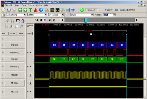
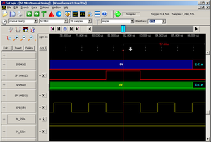
.The screenshot below shows the SPI master (the
LTC5800
platform) transfering 8 bytes of data (0x0001020304050607)- There is no slave attached. The
MISOline stays high and the master therefore always receives0xffffffffffffffff. - The
CLKfrequency is set to the 1/16th of the CPU clock frequency. With a CPU clock at 7.4MHz, theCLKperiod is 2.16us. - Sampling is set up to happen on a rising edge.
- The
SS0npin is used for theCSline. - Data is sent most-significant-bit (msb) first, i.e. 5 is encoded as
b00000101.
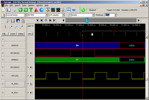
The following shows some of the settings of the SPI master module.
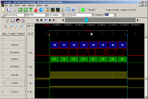 |  |
the SS0n pin is used as CS line | the SS1n pin is used as CS line |
| 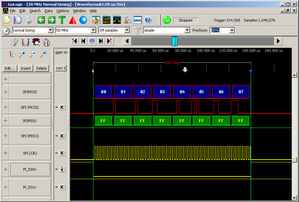 |
| most-significant-bit (msb) first | least-significant-bit (lsb) first |
|  |
CLK line at 1/16th the CPU speed | CLK line at 1/8th the CPU speed |
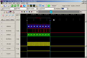
 |  |
sampling on the rising edge of CLK | sampling on the falling edge of CLK |
| 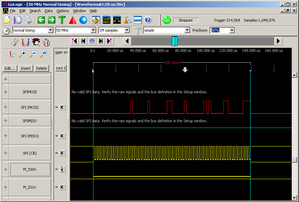 |
CLK is low when not in use | CLK is high when not in use |
The 02-spi Sample Application
The 02-spi sample application shows how to use SPI. Compile and load this application on your
When you run the application, each second:
- The following bytes are sent over the SPI bus:
0x000102030405060708 The device prints on the CLI what bytes have been sent and received
spi app, ver 1.0.0.1
SmartMeshIP stack, ver 1.2.1.3
SPI sent:     00 01 02 03 04 05 06 07
SPI received: 6f 70 71 72 73 74 75 76
SPI sent:     00 01 02 03 04 05 06 07
SPI received: 77 78 79 7a 7b 7c 7d 7e
SPI sent:     00 01 02 03 04 05 06 07
SPI received: 7f 80 81 82 83 84 85 86
SPI sent:     00 01 02 03 04 05 06 07
SPI received: 87 88 89 8a 8b 8c 8d 8e
SPI sent:     00 01 02 03 04 05 06 07
SPI received: 8f 90 91 92 93 94 95 96
In this setup, the
board is connected to an SPI slave device which returns ever-incrementing bytes.
The 02-spi_net Sample Application
The 02-spi_net sample application periodically sends the 4 bytes 0x00010203 over SPI, and sends the received bytes to the
SmartMesh manager
. You can configure the period between samples.The figure below is a typical CLI output:
spi_net app, ver 1.0.0.1
SmartMeshIP stack, ver 1.2.1.3
Current config:
 - period:  10000
 11037 : Joining
 11797 : Connected
 18084 : Active
SPI sent:     00 01 02 03
SPI received: 17 18 19 1a
SPI sent:     00 01 02 03
SPI received: 1b 1c 1d 1e
SPI sent:     00 01 02 03
SPI received: 1f 20 21 22
SPI sent:     00 01 02 03
SPI received: 23 24 25 26
in this case:
- period is 10000ms, i.e. the application sends one packet to the
SmartMesh manager
every 10s.
You can connect the ApiExplorer application to your
SmartMesh manager
to see the data received: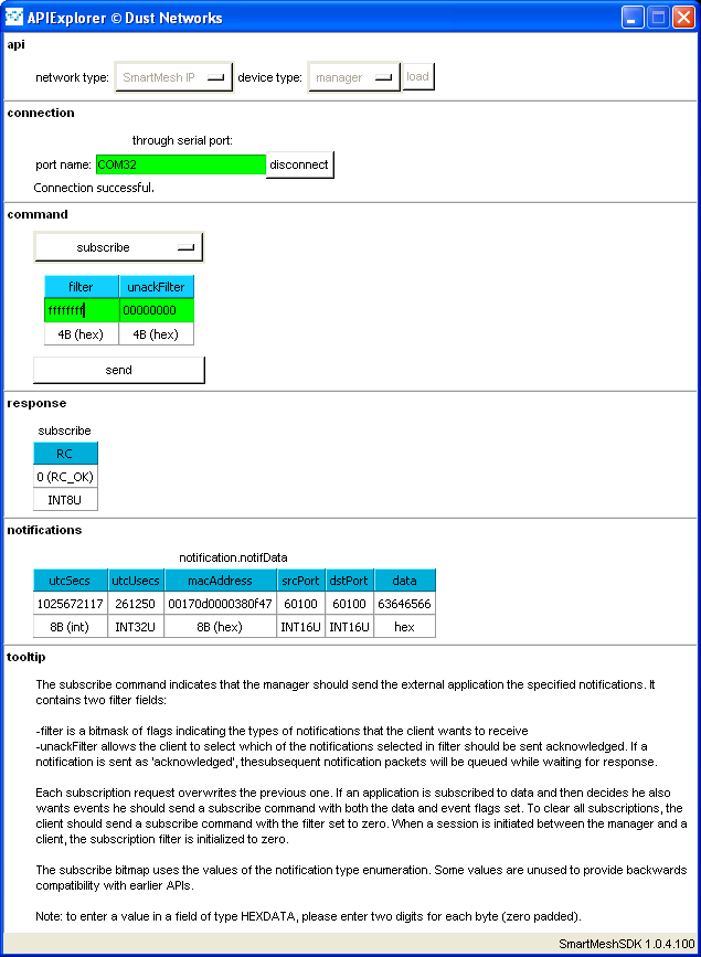
At any time, you can change the configuration values through CLI:
- type
period 5000to publish every 5s.
How the 02-gpio_net sample application registers to extra CLI commands is covered in the CLI module section.
Refer to the
SmartMesh On-Chip API html documentation
in the /doc directory of the for documentation about this feature.