I2C
This section refers to the following sample application(s):
02-i2c
The Inter-Integrated Circuit (I2C) bus is a digital communication bus used to attach low-speed electronic components.
The I2C bus is a two-wire bus.Communication is always initiated by a master but can be bidirectional to get data from slaves. The I2C bus uses the following data lines:
SCL: Clock to synchronize data transmission.SDA: Data transmitted in sync with the clock.
I2C on
LTC5800
The
On-Chip Software Development Kit
libraries allow your application to use the I2C in master mode. The I2C bus is exposed on the following pins on .| SCL | SDA |
|---|---|
| S SCK/SCL | S SSn/SDA |
The figure below is a screen capture of a logic analyzer which shows an I2C write transaction. Here the
LTC5800
chip sends three bytes of data (0x80 , 0x81, 0x82) to an I2C slave at address 0x05. The transaction starts with a start byte to indicate the address of the slave to talk to, and the direction (here "write").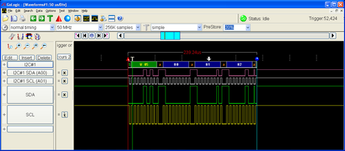
The figure below illustrates a "read" transaction. The
LTC5800
chip starts by sending a header byte containing the address of the slave to read from (here0x05), as well as the "read" bit. The LTC5800
chip (the I2C master) then sends a clock signal which the slave uses to time the bits it sends back over the SDA line to the master. In this case, the slave returns the bytes0x2A , 0x2B, 0x2C.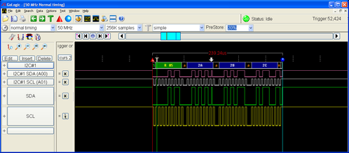
Some I2C device documentation will describe the 7-bit address as though it is already shifted left to accommodate the read/write bit (which is b0 of the address word). The OCSDK driver expects the 7-bit address to be right justified. E.g. The Sensirion SHT21 documentation gives the device address (in binary) as 1000 000 - the driver is expecting to see 0x40, not 0x80.
The 02-i2c Sample Application
This sample application creates a single task (called i2cTask) which, every second, alternates between sending three bytes and reading three bytes from an I2C slave at address 0x05. The logic analyzer screenshots above were obtained by running this sample application.
The task automatically starts communicating with the I2C slave when the application is started. It prints the bytes sent and received over the I2C connection.
i2c app, ver 1.0.0.2
SmartMeshIP stack, ver 1.2.1.6
Sent to I2C slave 05: 0x808182
Received from I2C slave 05: 0x262728
Sent to I2C slave 05: 0x808182
Received from I2C slave 05: 0x292a2b
Sent to I2C slave 05: 0x808182
Received from I2C slave 05: 0x2c2d2e
Sent to I2C slave 05: 0x808182
Received from I2C slave 05: 0x2f3031
The application will print an error when no slave with address 0x05 is present on the I2C bus. The I2C_SLAVE_ADDR defined at the top of the sample application's main file allows you to easily change the address of the I2C slave.
Refer to the
SmartMesh On-Chip API html documentation
in the /doc directory of the for documentation about this feature.