Part 4: Interact with Sensors and Actuators
Goal
Connect sensors and actuators to your mote, and interact with them from your Node-RED instance in the IBM Cloud!
The Setup
You will be working "in the cloud": you will create a Node-RED application on your private IBM Cloud instance which interacts with the motes you have in the room.

On IBM Cloud, or anywhere else!
We use your Node-RED instance on IBM Cloud to show interaction from outside the classroom (here from the UK IBM datacenter). Of course, that Node-RED instance could have been running on any Internet-connected computer in the world.
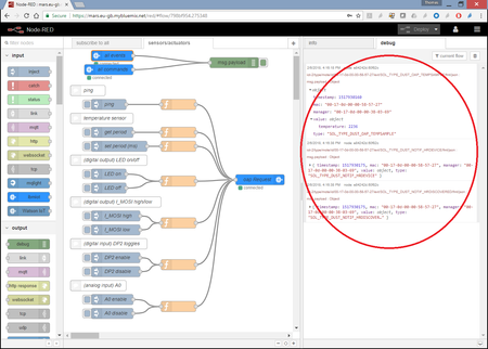
Install and Configure the Node-RED flow
Goal
You will find a functional Node-RED flow in the source code you downloaded. In this section, you will install it into your Node-RED instance on IBM Bluemix, and configure it to connect to our Watson IoT Platform, and talk to your manager and mote.
Install the pre-built flow
- Open your Node-RED instance on IBM Cloud
- Also open http://mars.solsystem.io/red/
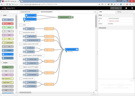
- Navigate to the "sensors/actuators" tab
- select all (Ctrl+A)
- Open the hamburger menu, export, clipboard
- copy the contents of that clipboard (Ctrl+C)
- On your Node-RED instance
- Open the hamburger menu, import, clipboard
- paste (Ctrl+V), and click Import
You now have a copy of that flow running on your Node-RED instance
Crash Course 33.4.1 (given by your instructor)
Walk-through of the flow.
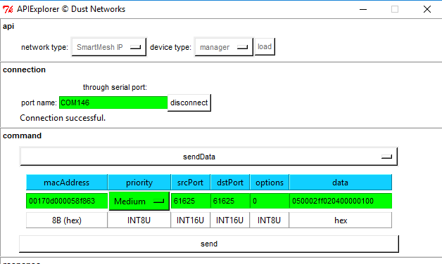
Configure the API Key and Authentication Token
- Ask you instructor the "API key" and "Authentication Token" to use
- In the Node-RED flow, double-click on "all events", then on the pen next to "API Key"
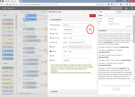
- Enter the "API Key" and "API Token", click update
- Click "Deploy", make sure all three ibmiot boxes appears as "connected"
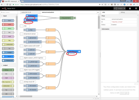
Configure the mote you will interact with
- Pick up one of your boards
- You can read the last 3 bytes of its MAC address (e.g. "38-07-0c") on the sticker above the main chip
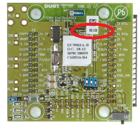
Its MAC address starts with "00-17-0d-00-00" and ends with what's on the sticker. So in my case the MAC address of my mote is "00-17-0d-00-00-38-07-0c".
What is the MAC address of your mote?
Use lower-case characters only!
The Watson IoT Platform is case sensitive, so MAC address "00-17-0d-00-00-38-07-0c" is different from "00-17-0d-00-00-38-07-0C". By convention, we use lower-case characters only.
- In the Node-RED flow, double-click on the "all events" ibmiot node, and enter your mote's MAC address in the Device ID field
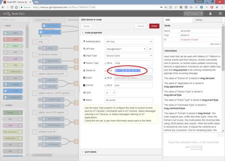
repeat for the "all commands" and "oap Request" nodes
Click "Deploy"
Beware of inactive debug nodes!
The debug nodes in Node-RED can be active or inactive. If your debug node is inactive, if will not print anything in the debug tab!
active inactive
What just happened?
Congratulations! You are now running a Node-RED application somewhere on the Internet which can send commands and receive events/responses for a particular mote.
Interact with your mote
Goal
You will now interact with your mote directly over the wireless network. Finally!
Just listen, will you!
- Sit back and relax for a couple of minutes, while watching the debug pane fill up
What are the types of events you receive from your mote?
Crash Course 33.4.2 (given by your instructor)
About limits of up/downstream packets.
What is the temperature at your mote?
Ping your mote
- Press the "ping" inject node. This sends a request for the mote to answer with its "info"
Don't go beyond 1 downstream packet per second!
There are many settings that allow you to increase the number of downstream packets sent per unit of time (packet sent from the manager into the network). To be on the safe side, don't send more than one packet per second in this course.
What does your mote respond?
Crash Course 33.4.3 (given by your instructor)
About "oap", "oapResponse" and "token"
Get/set the period at which the note reports temperature
- Press the "get period" inject node. This sends a request for the mote to answer with its configuration of its built-in temperature sensor
How often does the mote generate a temperature measurement?
- You can set the period using in the "set period (ms)" but be aware of the maximum number of packets generated in the network.
- Make sure to return a 30s temperature reporting interval.
Set/clear the blue LED
Set the "LED EN" jumper!
On the DC9003 board, the LED can only go on when the "LED EN" jumper is installed. You know your jumper is installed and the mote operational when both green LEDs are on.
- Click the "digital out: set LED" button. Ensure the blue LED goes on.
- Click the "digital out: clear LED" button. Ensure the blue LED goes off.
Set/clear the I_MOSI pin
Never connect power to ground!
You will be moving wire jumpers around. If you use a jumper to connect power to ground, you will damage the chip and the board. Be very careful!
All ground pins are labeled "GND".
Power pins are labeled "VSUPPLY", "VBAT" or "VUSB_3V6".
Don't touch the "V+" and "+5V" pins!
The "V+" and "+5V" pins are higher-voltage pins used for exotic applications. Never connect a jumper wire to them.
The LED is just connected to a digital output pin on the micro-controller. Just like the LED, you can control several other digital output pins, including the one labeled "I_MOSI".
There are many ways to verify whether a pin is "high" or "low". One fun way is to connect a buzzer to it.
- Using your buzzer and two jumper wires, create the following circuit:
- Click the "digital out: set I_MOSI" button. Ensure the buzzer sounds.
- Click the "digital out: clear I_MOSI" button. Ensure the buzzer stops sounding.
Need more pins?
Read the SmartMesh IP Tools Guide (http://www.linear.com/docs/42453), Chapter "On-chip Application Protocol", Section "Addressable Elements and Pinout" for a full list of pins you can use.
Receive an event on a digital input pin state change
You can switch several pins as digital input pins. One example is the pin labeled "DP2". When enabled, the mote generates an event each time the pin changes state, i.e. each time the pin is pulled high or low.
- Click the "digital in: enable DP2" button to send a message to enable the DP2 pin as an digital input.
Connect a jumper wire between "DP2" and "GND". Make sure you receive an event. What does it contain?
Connect a jumper wire between "DP2" and "VSUPPLY". Make sure you receive an event. What does it contain?
Periodically read an analog input
- Use the "A0 enable" button to enable the A0 input
how often is the mote going to generate an analog measurement?
The range of the analog input is 0V to 1.8V. Never exceed that range. You can safely tie the A0 ADC channel to a ground, but never tie is to VSupply.
- Connect the A0 ADC input ot GND.
What is the voltage reported by the mote?
- Make sure to disable the analog input when you're done.
What just happened?
Congratulations! You have now mastered the base techniques to remotely interact with GPIO pins (both input and output) and ADC channels!
And while you can build great applications with just that capability (Part 5: Programming Challenge is an example), you've just touched the surface of what you can do. Interfaces you haven't used include SPI, I2C, 1-Wire, UART and ADC.
Check out the following recipes about interfacing external sensors:
-
Interface your Mote to a Thermocouple — We use the DC9005 Eterna QuikEval Adapter to connect the mote to an LTC2984 Multi-Sensor High Accuracy Digital Temperature Measurement System Demo Board to read a K-type thermocouple.
-
Deep-dive into the OAP Protocol — The “On-chip Application Protocol“ (OAP) runs on all SmartMesh IP motes running in Master mode. See how you can interact with it to sample temperature, set/get the state GPIO pins, and trigger ADC readings.
-
Interface your mote to a CC3200 — Interface a CC3200 to a mote using the SmartMesh C library!
-
Interface your mote to a Force-Sensitive Resistor — An example On-Chip Software Development Kit project in which we integrate a low-cost force-sensitive resistor.
-
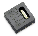
Interface your Mote to a Sensirion Temperature/Humidity Sensor — Sensirion I2C temperature/humidity sensors are almost trivially easy to use with the On-Chip SDK. In this recipe, we connect a mote to the SHT21.
-
Adding Bluetooth Low-Energy Connectivity to a Mote — We detail how we used an nrf8001 Bluetooth low-energy (BLE) breakout board from Adafruit to demonstrate remote configuration of a mote.