...
| Device Name | Special Function |
| LTC5800 chip | LTP5901/2 board | |||||||||
| Header | Silkscreen text | pin name | pin number | pin name | pin number | ||||||||
|---|---|---|---|---|---|---|---|---|---|---|---|---|---|
DN_GPIO_PIN_0_DEV_ID | SPI Master Slave Select 2 (active low) | P2 |
| DP0/GPIO0 | 36 | DP0 | 28 | ||||||
DN_GPIO_PIN_3_DEV_ID | IPCS Slave Select | P1 | I SSn | IPCS_SSn | 45 | IPCS_SSn/GPIO3 | 39 | ||||||
DN_GPIO_PIN_4_DEV_ID | IPCS Clock | P1 | I SCK | IPCS_SCK | 44 | IPCS_SCK/GPIO4 | 36 | ||||||
DN_GPIO_PIN_5_DEV_ID | IPCS Master-Out-Slave-In | P1 | I MOSI | IPCS_MOSI | 42 | IPCS_MOSI/GPIO5 | 35 | ||||||
DN_GPIO_PIN_6_DEV_ID | IPCS Master-In-Slave-Out | P1 | I MISO | IPCS_MISO | 40 | IPCS_MISO/GPIO6 | 33 | ||||||
DN_GPIO_PIN_9_DEV_ID | SPI Master Master Clock | P3 | M SCK | SPIM_SCK | 43 | SPIM_SCK | 41 | ||||||
DN_GPIO_PIN_10_DEV_ID | SPI Master Master-Out-Slave-In | P3 | M MOSI | SPIM_MOSI | 41 | SPIM_MOSI | 40 | ||||||
DN_GPIO_PIN_11_DEV_ID | SPI Master Master-In-Slave-Out | P3 | M MISO | SPIM_MISO | 39 | SPIM_MISO | 38 | ||||||
DN_GPIO_PIN_12_DEV_ID | SPI Master Slave Select 0 (active low) | P3 | M SS0n | SPIM_SS_0n | 47 | SPIM_SS_0n | 44 | ||||||
DN_GPIO_PIN_13_DEV_ID | SPI Master Slave Select 1 (active low) | P2 | M SS1n | SPIM_SS_1n | 46 | SPIM_SS_1n | 43 | ||||||
DN_GPIO_PIN_16_DEV_ID | P2 | PWM0 | PWM0 | 49 | PWM0 | 46 | |||||||
DN_GPIO_PIN_20_DEV_ID | P2 | DP1/IO20 (D5/D8 LEDs) | DP1 | 48 | DP1 | 45 | |||||||
DN_GPIO_PIN_21_DEV_ID | P2 | DP2 | DP2 | 34 | DP2/GPIO21 | 26 | |||||||
DN_GPIO_PIN_22_DEV_ID | P2 | DP3/IO22 (D7/D10 LEDs) | DP3 | 33 | DP3 | 25 | |||||||
DN_GPIO_PIN_23_DEV_ID | P2 | DP4 (D6/D9 LEDs) | DP4 | 27 | DP4 | 21 | |||||||
DN_GPIO_PIN_26_DEV_ID | SPI Slave Master-Out-Slave-In | P2 | S MOSI | SPIS_MOSI | 51 | GPIO26/SPIS_MOSI | 48 | ||||||
...
- The gpioToggleTask() task configures a pin as output and toggles its state every second. On the
board, this corresponds to the blue LED.Include Page _def_board_fraser _def_board_fraser - The gpioNotifTask() task waits for notifications from a different pin configured as input. On the
board, this corresponds to the pin labeledInclude Page _def_board_fraser _def_board_fraser DP2on the silkscreen. Connecting this pin to the supply voltage triggers a notification; disconnecting it triggers another one, as shown in the CLI output captured below:
...
| No Format |
|---|
gpio app, ver 1.0.0.1 SmartMeshIP stack, ver 1.2.1.3 gpioNotifTask: level=1. gpioNotifTask: level=0. |
| Note |
|---|
The |
The 02-gpio_net Sample Application
The 02-gpio_net sample application periodically reads the state of a pin, and sends a corresponding packet to the manager. You can configure the period between samples, and the 1-byte value to send when the pin is high or low.
The figure below is a typical CLI output:
| No Format |
|---|
gpio_net app, ver 1.0.0.1 SmartMeshIP stack, ver 1.2.1.3 Current config: - lowval: 255 - highval: 1 - period: 10000 6661 : Joining 8808 : Connected 15096 : Active samplePinLevel=0, sent 0xff samplePinLevel=0, sent 0xff samplePinLevel=0, sent 0xff samplePinLevel=1, sent 0x01 samplePinLevel=1, sent 0x01 samplePinLevel=1, sent 0x01 |
In this case:
- period is 10000ms, i.e. the application sends one packet to the manager every 10s.
- highval is 255, i.e. the application sends the 1-byte payload
0xffto the manager when the pin is high. - lowval is 1, i.e. the application sends the 1-byte payload
0x01to the manager when the pin is low.
In the figure above, the pin was tied to ground for the first 30s, then tied high for the next 30s.
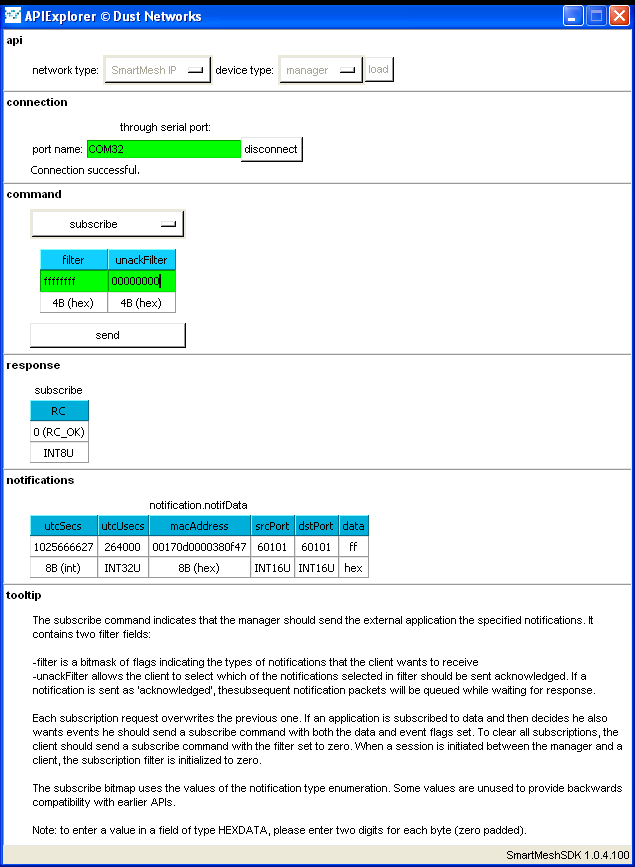
You can connect ApiExplorer to your
| Include Page | ||||
|---|---|---|---|---|
|
At any time, you can change the configuration values through CLI:
- type "
period 5000" to publish every 5s. - type "
highval 10" to send byte0x0awhen the pin is tied high. - type "
lowval 11" to send byte0x0bwhen the pin is tied low.
| Info |
|---|
How the |
| Include Page | ||||
|---|---|---|---|---|
|